
SENIOR DESIGN
Fall 2020
This section serves as an active portfolio of Amy's engineering projects in her ME460 Senior Design course at Boston University College of Engineering. Scroll down to view her design projects.
PROJECT #1
LINEAR STAGE WITH
OPEN-LOOP CONTROL
AN INTRODUCTION TO THE PROJECT
PROJECT GOAL
The goal of this design project is provide students with the necessary materials and knowledge to construct an automated linear stage capable of moving through a predefined sequence of motion while carrying a load up to 0.5kg. Students will have written the Arduino programs themselves, integrating the motion control of the stepper motor with the linear position of its carriage through open-loop control. For most students, this will be new material they are being introduced, thus a learning curve to achieve.
MY PROJECT PROCESS
The sections below detail my design process, the mechanical construction of my linear stage, the electrical connections, and an explanation of my code. I had prior experience with Arduino from my ME360 Product Design course and have worked with stepper motors during a summer research internship. While I had minimal exposure with assembling a linear stage, I found that part of the design process very enjoyable. I was surprised by how much creativity this project would take, as well as a lot of troubleshooting.
MATERIALS USED
NEMA 17 Stepper Motor 50oz.in
Arduino UNO and Arduino motor shield
Foamboard, 8inX10in, 5pack
Linear motion set
TMEZON 12V, 2A power adapter
X-ACTO Knife
TILSWALL 50W Hot Glue Gun
Push pins
Allen wrenches
Breadboard and jumper wires
Pushbutton switches (from Arduino kit)
Pigtail connector

THE DESIGN PROCESS
THE FOUNDATION
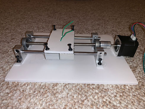
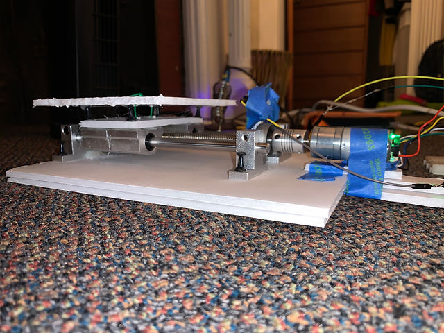
The picture on the left shows the foundation of my linear stage. On the very bottom is a sheet of foam-board that serves as the base. Later in the design process, a second layer of foam-board to provide added support. Starting at the left moving right are two sets of light silver bearings (on each side) that support two smooth rods. These rods/bearings are support railings that help eliminate any wobbling from the motor. Supported on those bearings is a dark grey bearing that holds the lead screw. This lead screw is what the linear stage is driven on, and it holds a brass support (not seen) that moves back and forth on the stage. On the right side of this stage is the motor and its support bearing. The stepper motor receives input signals from the Arduino UNO and converts them into mechanical shaft rotations. And finally, the last portion of the foundation is the base carriage. This base carriage is comprised of two sets of linear slide bearings that are hot glued and pinned to a foam board. The linear slide bearings glide on the support rods, making it so that lead screw can drive this base carriage up and down. The brass support (not seen) is connected to the carriage with a thick wire wrapped around its spokes and threaded through the foam-board.
CONNECTION METHODS
The image on the right is an example of the connection methods used to join my linear stage together. Black push pins connected the silver bearings (image above) to the foam-board and they were also used to connect the base carriage to the linear slide bearings. Hot glue was also used as a further stabilization method. Hot glue was poured into the bearing holes before the push pins were inserted to create a firm hold. The foam-board on the carriage was also hot glued to the linear slide bearings to ensure that the carriage would move as one piece, and not like it are four independent pieces.


THE CARRIAGE
The image on the left displays the complete carriage system of the linear stage. The top carriage is a 5in by 5in piece of foam-board with a green wire threaded through it from the brass support underneath the base carriage. The top carriage rests on four black push pins that hold the base carriage down. The top carriage is secured with hot glue on the pins and the threaded green wire.
THE BRASS SUPPORT
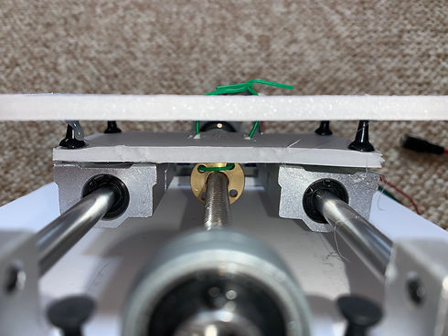
The image on the right is a clear shot of the brass support spoken often about in this design section. The brass support sits on the lead screw that is controlled by the stepper motor. A green wire is threaded between two of the spokes and then also threaded through two foam-boards. This connection drives the carriage back and forth on the linear stage and this one small part is considered to be the driving force of this entire linear stage.

THE PUSH BUTTON
The image on the left focuses on an integral portion of this project, the push button which is attached to the base of my linear stage with a rubber mount and masking tape. The push button, the small black and silver switch attached to the blue eraser, works by sending an electrical signal "TRUE" to the Arduino UNO whenever it is pressed. In this project, a deliverable was to have the push button start and end a homing sequence on the linear stage. This means when the button is pressed, the motor begins to turn and send the carriage forward until it runs into and pressed the button again. The carriage retracts and moves forward again until it hits the push button for a final and third time. The carriage then moves backwards as it ends its homing sequence. The push button was placed in front of the carriage support rods to ensure that the button is pressed in every trial. The silver support bearings offer a firm but consistent press versus the flexible foam-board that the carriage is made of; for that reason the button was mounted in a secure location that provided an accurate press every time.
PUSH-BUTTON ELECTRICAL WIRING
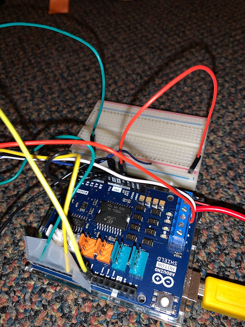
The image on the right shows how the push-button switch is connected to the Arduino UNO. In the first few attempts to integrate the switch into the project, the switch was originally mounted and connected onto a breadboard. The breadboard offered stability in electrical connections, however it was very difficult to mount onto the linear stage and ultimately the breadboard was discarded. Afterwards, with the use of Google, the decision to mount the push-button by itself onto the stage was proposed. The push-button switch was sautered to two jumper wires. One jumper wire connects the switch to ground on the Arduino. The other wire connects to a 1k resistor and then into digital pin 2 on the Arduino. It is very important to have a resistor in this connection because it helps regulate the current in the system.

THE FINAL ASSEMBLY
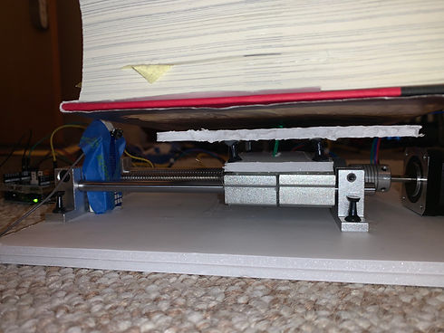
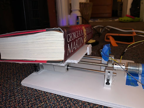
The image on the left depicts the final assembly and 0.5kg load of my linear stage project. The foam carriage, supported by silver linear slide bearings and a lot of hot glue and push pins, carries a heavy book back and forth on an autonomous linear stage. The linear stage is controlled by a stepper motor that drives the stage back and forth until it pushes the push-button switch and sends a trigger back to the Arduino UNO. The Arduino reads the signal and sends a message to the motor to move forward until it hits the button for a final time. The linear stage then drives backward and ends its stepping process. Throughout the final design step, this stage was tested multiple times to ensure the button as pressed with sufficient force.
THE STEPPING CONTROL SEQUENCE
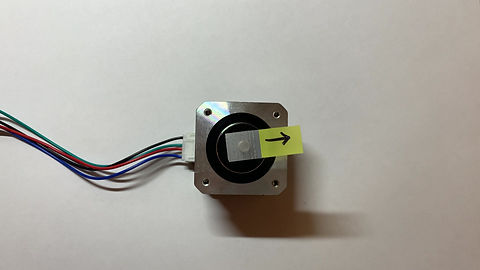
Students were tasked to create a computer program that controlled the stepper motor in various stepping sequences. Students used an Arduino UNO and electrical wiring to program the stepper motor, keeping in mind voltage and speed limits as to not melt the Arduino motor shield. The NEMA 17 Stepper motor used in this design project operates in a stepping motion cycle. A stepper motor is an electromechanical device that takes converts digital pulses into mechanical shaft rotations. Students program the number of rotations they want the motor to turn using an Arduino program. The motor can operate in various stepping schemes, though for this only full-stepping and half-stepping sequences were analyzed.
FULL-STEPPING SEQUENCE
The full-step control sequence is a high torque, fast motion. In this mode, two phases of the stepper motor are energized at the same time, the other two phases are not energized. As a result of these two energized phases, the current flowing into the motor and the magnetic field generated are quite strong, making this stepping mode favorable for high intensity motion. If you would like your motor to move at the fastest speed possible, full-stepping is the mode you should select. However, the disadvantage to this mode is that the heat generated from the motor moving at full-speed is capable of melting your electronics, so an Arduino motor shield was necessary in this project. Likewise, the full-step has the potential to overshoot your position marker, making this motion less accurate.

HALF-STEPPING SEQUENCE
The half-step control sequence is a reduced torque motion with a step size that is reduced by half; if full-step is 100 rotations, half-step is 50 rotations. In this mode, only one phase of the stepper motor is energized, which is why the torque is lesser and produces a slower speed. This motor mode is great for troubleshooting projects because the low torque produces less heat , making it safer for your electronics. A drawback to this mode however is that the torque in half-step is not constant because only one phase of the motor is energized and it cannot provide a consistent flow of current. In this design project, half-step control sequence was the preferred mode because it provided a reliable enough output for the linear stage and did not overheat the Arduino UNO.
RESULTS & THE CODE
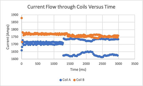
CURRENT FLOW VS TIME GRAPH
This graph shows how the current of the coils of the stepper motor changes against time. The data that was used in this graph was modified to eliminate any abnormalities. For example, the graph shows the current through the coils only while the coils are energized.
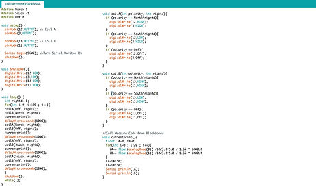
CURRENT COIL MEASURING CODE
This code is modified from the code available to the class on Blackboard. This code measures the current flow through the coils of the stepper motor against time. This test is especially important because it measures the current while the coils are energized only.
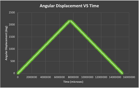
ANGULAR DISPLACEMENT VS TIME GRAPH
This graph shows the displacement of the stepper motor against time. It shows how a motor moves when it is energized and then how when it becomes less energized, how little it moves.

DISPLACEMENT MEASURING CODE
The code above is modified code from the code given to the class on Blackboard. This code controls and measures the displacement of the stepper motor against time.
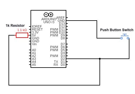
ELECTRICAL DIAGRAM
The diagram above shows the electrical relationship of the push-button switch in this linear stage project. The switch is connected to the Arduino by two wires. One of the wires connects the switch to the ground. The other wire connects into digital pin 2 AND a 1k resistor. The resistor is incredibly important in this electrical system because it helps regulate the current flow from the switch to the Arduino to the motor.

HALF-STEPPING SEQUENCE CODE
The code above is modified from the code available to the class from Blackboard. This code regulates the number of mechanical rotations the stepper motor will undergo. In the void loop section, students can change the count number to change the number of steps the motor will do. In this case, the code is set to run in half-step, half of a normal speed.

FULL-STEPPING SEQUENCE CODE
The code above is modified from the code available to the class from Blackboard. This code regulates the number of mechanical rotations the stepper motor will undergo. In the void loop section, students can change the count number to change the number of steps the motor will do. In this case, the code is set to run in full-step, the fastest speed the motor can run.

THE FINAL CODE
The image above is the complete code used in my homing sequence. The code initializes the Arduino pins and creates a shutdown function to power off the motor. Then in the loop, the code waits until the push-button has been pressed, then it energizes the coils to move forward, press the button, move back and then press the button AGAIN, and finally return back to its original position. At the end of the code is a modified function from Blackboard that sets the coil polarities.
THE FINAL PRODUCT
The video on the left is proof that my linear stage works with an open-loop control holding a (heavy) 0.5kg load.
PROJECT #2
LINEAR STAGE W/
CLOSED-LOOP CONTROL
AN INTRODUCTION TO THE PROJECT
PROJECT GOAL
The goal of this design project is provide students with the necessary materials and knowledge to construct an automated linear stage capable of moving through a predefined sequence of motion while carrying a load up to 0.5kg. Students will have written the Arduino programs themselves, integrating the motion control of the stepper motor with the linear position of its carriage through closed-loop control. For most students, this project is an iteration of our previous design project.
MY PROJECT PROCESS
The sections below detail my design process, the mechanical construction of my linear stage, the electrical connections, and an explanation of my code. I had prior experience with Arduino from my ME360 Product Design course and have worked with stepper motors during a summer research internship. While I had minimal exposure with assembling a linear stage, I found that part of the design process very enjoyable. I was surprised by how much creativity this project would take, as well as a lot of troubleshooting.
MATERIALS USED
Encode Motor
Arduino UNO and Arduino motor shield
Foamboard, 8inX10in, 5pack
Linear motion set
TMEZON 12V, 2A power adapter
X-ACTO Knife
TILSWALL 50W Hot Glue Gun
Push pins
Allen wrenches
Breadboard and jumper wires
Pushbutton switches (from Arduino kit)
Pigtail connector
THE DESIGN PROCESS
THE FOUNDATION
The picture on the left shows the foundation of my linear stage. On the very bottom is a sheet of foam-board that serves as the base. Later in the design process, a second layer of foam-board to provide added support. Starting at the left moving right are two sets of light silver bearings (on each side) that support two smooth rods. These rods/bearings are support railings that help eliminate any wobbling from the motor. Supported on those bearings is a dark grey bearing that holds the lead screw. This lead screw is what the linear stage is driven on, and it holds a brass support (not seen) that moves back and forth on the stage. On the right side of this stage is the motor and its support bearing. The stepper motor receives input signals from the Arduino UNO and converts them into mechanical shaft rotations. And finally, the last portion of the foundation is the base carriage. This base carriage is comprised of two sets of linear slide bearings that are hot glued and pinned to a foam board. The linear slide bearings glide on the support rods, making it so that lead screw can drive this base carriage up and down. The brass support (not seen) is connected to the carriage with a thick wire wrapped around its spokes and threaded through the foam-board.
CONNECTION METHODS
The image on the right is an example of the connection methods used to join my linear stage together. Black push pins connected the silver bearings (image above) to the foam-board and they were also used to connect the base carriage to the linear slide bearings. Hot glue was also used as a further stabilization method. Hot glue was poured into the bearing holes before the push pins were inserted to create a firm hold. The foam-board on the carriage was also hot glued to the linear slide bearings to ensure that the carriage would move as one piece, and not like it are four independent pieces.
THE CARRIAGE
The image on the left displays the complete carriage system of the linear stage. The top carriage is a 5in by 5in piece of foam-board with a green wire threaded through it from the brass support underneath the base carriage. The top carriage rests on four black push pins that hold the base carriage down. The top carriage is secured with hot glue on the pins and the threaded green wire.
THE BRASS SUPPORT
The image on the right is a clear shot of the brass support spoken often about in this design section. The brass support sits on the lead screw that is controlled by the stepper motor. A green wire is threaded between two of the spokes and then also threaded through two foam-boards. This connection drives the carriage back and forth on the linear stage and this one small part is considered to be the driving force of this entire linear stage.
THE PUSH BUTTON
The image on the left focuses on an integral portion of this project, the push button which is attached to the base of my linear stage with a rubber mount and masking tape. The push button, the small black and silver switch attached to the blue eraser, works by sending an electrical signal "TRUE" to the Arduino UNO whenever it is pressed. In this project, a deliverable was to have the push button start and end a homing sequence on the linear stage. This means when the button is pressed, the motor begins to turn and send the carriage forward until it runs into and pressed the button again. The carriage retracts and moves forward again until it hits the push button for a final and third time. The carriage then moves backwards as it ends its homing sequence. The push button was placed in front of the carriage support rods to ensure that the button is pressed in every trial. The silver support bearings offer a firm but consistent press versus the flexible foam-board that the carriage is made of; for that reason the button was mounted in a secure location that provided an accurate press every time.
PUSH-BUTTON ELECTRICAL WIRING
The image on the right shows how the push-button switch is connected to the Arduino UNO. In the first few attempts to integrate the switch into the project, the switch was originally mounted and connected onto a breadboard. The breadboard offered stability in electrical connections, however it was very difficult to mount onto the linear stage and ultimately the breadboard was discarded. Afterwards, with the use of Google, the decision to mount the push-button by itself onto the stage was proposed. The push-button switch was sautered to two jumper wires. One jumper wire connects the switch to ground on the Arduino.
THE FINAL ASSEMBLY
The image on the left depicts the final assembly and 0.5kg load of my linear stage project. The foam carriage, supported by silver linear slide bearings and a lot of hot glue and push pins, carries a heavy book back and forth on an autonomous linear stage. The linear stage is controlled by a stepper motor that drives the stage back and forth until it pushes the push-button switch and sends a trigger back to the Arduino UNO. The Arduino reads the signal and sends a message to the motor to move forward until it hits the button for a final time. The linear stage then drives backward and ends its stepping process. Throughout the final design step, this stage was tested multiple times to ensure the button as pressed with sufficient force.
RESULTS & THE CODE

LINEAR VELOCITY VS TIME GRAPH
This graph shows how the encoder moves along its linear slide against time. Because of how an encoder motor works, its current pulses are shown in this graph.

LINEAR DISPLACEMENT VS TIME GRAPH
This graph shows the displacement of the encoder motor against time. It shows how a motor moves when it is energized and then how when it becomes less energized, how little it moves.

ELECTRICAL DIAGRAM
The diagram above shows the electrical relationship of the push-button switch in this linear stage project.

THE FINAL CODE
The image above is the complete code used in my homing sequence. The code initializes the Arduino pins and creates a shutdown function to power off the motor. Then in the loop, the code waits until the push-button has been pressed, then it energizes the coils to move forward, press the button, move back and then press the button AGAIN, and finally return back to its original position.
THE FINAL PRODUCT
The video on the left is proof that my linear stage works with a closed-loop control holding a (heavy) 0.5kg load.