PRODUCT DESIGN
Spring 2020
This page serves as a complete portfolio of Amy's ME360 Product Design course at Boston University's College of Engineering. Throughout the course, she completed four team projects that tested her capabilities with computer aided design (CAD), Arduino scripts, 3D printing, thermal imaging.
ASSIGNMENT #1 - GASKET
The purpose of this assignment is to cultivate and refine important skills necessary for accurate product designs. Students practice taking precise measurements of a gasket using a caliper, create fully dimensioned engineering sketches, recreate these sketches on a CAD software, and convert their CAD file to G Code using the software Gibbs Cam. Finally, students machine their part on a CNC Mill and return to class to test if they correctly measured the features on their gaskets. If the students completed the assignment correctly, their gaskets should fit flush and not obscure any of its features.
In industry and academia research, it is crucial that students know how to take accurate measurements. Many jobs require a high level of precision and will expect graduating seniors to accurately recreate designs using CAD software. It is important to foster these skills in class where margins for error are wide and the stakes are a lot lower. Likewise, students should also familiarize themselves with the machines in typical machine shops like EPIC. Being comfortable using software like Gibbs Cam and machines like the CNC Mill will only help students in the future, impressing their future employers.

THE SKETCH
To create this sketch, I took the measurements of every feature first. I measured the length, widths, and diameters when applicable. Many of the features shared the dimensions, making taking measurements a lot easier. Secondly, I measured the distance of the features from the edges, marking both the x and y positions. Lastly, I took measurements of the distance between features themselves as a safety precaution when recreating my sketch on CAD. I wanted to make sure I could have secondary measurements to double check the accuracy of the position of the measurements. When I completed taking measurements, I recreated the part on Creo and created a drawing. I fully dimensioned my sketch and it is shown above.

THE COMPLETED PRODUCT
After I created my CAD file and drawing, I took both items to EPIC and sat down with as student worker to convert my CAD part into G Code using the software Gibbs Cam. Gibbs Cam allowed me to visualize my part going through the machining process, from picking the tools and RPM speeds to seeing the process digitally in the visualizer. It was incredibly interesting to go through the process myself and see how to convert a CAD part into something that can be machined. After receiving my G Code file, I took it to the CNC Mill and inserted my code. From there, the mill read the file and recreated the process onto a piece of PVC. Shown above is my finished product.

THE RESULTS
Unfortunately despite my best efforts, my gasket measurements were off slightly. The measurements for the pinholes were too small. While the pins could enter the holes, it was a tight fit and made placing the gasket on very difficult. In the future, I will make any pinholes larger than my original dimensions, by about 0.051 inches in diameter to insure a looser fit. Likewise, the larger rectangle dimensions were overshot by approximately by 0.081 inches tall which is shown in the image above. Other than that, my gasket fit quite well and this project was overall a success.
ASSIGNMENT #2 - HOT WIRE TOOL
The purpose of this assignment is to introduce students to the complex process of product design for a hot wire tool. Students working on a team learn and use molding, casting, and soldering techniques to create the heating component of the tool which is comprised of plaster of paris and a nichrome wire to conduct electrical current. Students conceptualize a design for this tool using many different materials such as clay molding, 3D printing, and electrical components. Students also briefly studied ergonomic principles to design this hand tool based on popular palm sizes. At the end of this assignment, student teams will submit a physical working prototype of their hot wire tool to be tested on its functionality, maintenance, and appeal.
In industry and academia research, it is crucial that students learn to take a design prompt and conceptualize it into a working prototype. Future employers will expect mechanical engineers to have basic product design experience, and this introductory assignment is perfect for fostering those skills. Similarly, gaining experience on working on a diverse team is very important. Future employers look at a student's ability to collaborate effectively and professionally, and this assignment gives students the opportunity to work on those skills.


Sketch #1
Sketch #1 was ultimately the design we as a team decided to move forward with. Sketch #1 offered a neutral wrist grip that was preferred over Sketches #2, 3, and 4. Another benefit of this design is that its power grip allows for a relaxed hand posture so you can hold the tool for longer periods of time. Sketch #1 hit all the four categories of functionality, maintenance, usability, and appeal.
Sketch #2 & #3
The sketch above is both Sketch #2 and #3 because they were the same design, this sketch was chosen to be shown for its clarity. This design was not chosen because the screwdriver type angle of operating this tool was strenuous on the wrist. Sketch #1 offered a more relaxed grip. Sketch #2 and #3 only met the criteria of maintenance, functionality, and appeal; not usability.
This Sketch #2 is my sketch.
Sketch #3
Sketch #3 offered a saw-like design that was ultimately discarded the tip of the design structure interferes with cutting foam, doesn't allow for maximum reach. The nice aspect of this design however was the the grip that this tool provided, very easy to wield. Sketch #4 only met two criteria, maintenance and appeal; it did not meet functionality and usability.
THE CAD MODEL
The image to the right is our CAD (computer aided design) model of our Sketch #1. Using the software Creo we generated a to scale model of our part using rounding and chamfer tools. Our model also includes the method of fastening our part together; at the top and bottom of the model are screw holes that will be used to join the model together. After completing our model, we sliced it perfectly in half so that we can print the model in two separate parts and then join them together.

THE PROCESS
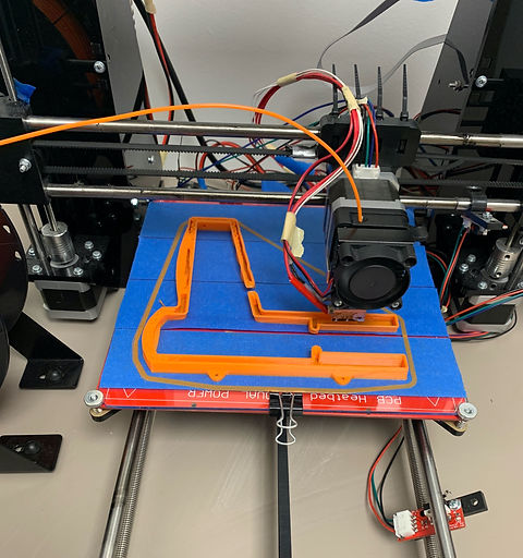
We utilized 3D printers to create the body of our hot wire tool. Shown here is the first of our many prototypes. A large issue that we faced in multiple printings of our part is that we neglected to add supports inside the body and as a flank. The supports inside the body are crucial because they provide support for the curved top of the part to print upon. Not adding supports made it difficult for the plastic to harden properly and made holes in the top surfaces. Similarly, not adding a flank meant that the plastic had to harden on the base of the 3D printer and oftentimes while the rest of the part was printing, the base would bend upwards - messing up the entire print and part.
THE COMPLETED PRINT
After multiple tries and consulting Professor Guiterrez-Wing, we successfully printed out our model. Shown here and explained earlier, we printed our part in two halves to join together which allows for easy maintenance. We allowed for space to hold our heating component and a slot for the button to be positioned. Our design allows includes grooves on the handle for improved usability and its overall sleek is very appealing. A video at the end of these images shows the prototype working properly, proving its functionality.


THE COMPLETED PROTOTYPE
The image on the left shows our completed prototype of the hot wire tool. Inside the model, the heating component is securely fastened to one side using silicone. The button is safely held in place using superglue. The model is joined together using screws in the threaded fastening holes. This model achieves all four design criteria of functionality, maintenance, usability, and appeal.

Results
Our prototype of a hand tool that uses the heat dissipated across a nichrome wire to conduct electrical current was a success. We utilized plaster of paris, 3D printing, soldering, silicone, and fastening tools to create this model. This model meets all of the design criteria and was very enjoyable to create. In the future this model could be improved by using stronger solvents to hold the internal components in place, and machine the part with a higher degree of accuracy 3D printer.
ASSIGNMENT #3 - ARDUINO CONTROLLER
The purpose of this assignment is to expose students to the complex design process that is creating an interactive product using the programming languages Arduino and Python. At completion of this project, students will have designed and built a device that receives real-world input (i.e. movement, sound, force) to control a software of their choice. Students programmed the software program Arduino UNO to receive and analyze data inputs from various sensors which it the turned into an output that the program Python would program as keystrokes on a computer. Students needed to consider ergonomic principles in the comfortability ad appeal of their product. Students were also called upon to use their CAD and 3D printing skills to create the body of their products. Lastly, students were able to develop their presentation skills when delivering their final technical presentation.
At the end of the group presentations for this project, it was incredible to see the variety of unique products that were created. One group created a device that converted the sound of a person breathing into decibel inputs that controlled the video game Temple Run. A soft breath activated the duck option, a fast hard breath signaled a jump in the game. This product is especially useful for individuals with limited mobility, such as paraplegics or amputees. This project made students think about the different ways you can interact with a device. This thought process is incredibly important in product design when you must think about the the target audience and usage of your product for consumer markets.
THE SKETCH
Our team chose to emulate Mike Tyson's Punch Out! game that was created by Nintendo in 1983. Our device was spilt into two components, a handheld control that activated the thrust "x" and "z" buttons and a chest plate that held the Arduino Uno and activated the left, right, and block motions. Our team chose this video game because of its limited controls and seemingly straightforward sensor options.

THE COMPLETED PROTOTYPE & RESULTS
At the completion of this project, our group was very impressed at what we accomplished and how well it worked. For the team members that worked on the programming portion, it was a new challenge to overcome and both students left with a new breadth of knowledge in Python and Arduino. For our team members who worked on the design portion, it was a difficult obstacle to think around the spring force limitation and was very satisfying when a working alternative was found. Every team member was equally challenged in all portions of this project.
While our product worked very well, future prototypes should refine the if-loops in the Python program that read the limit switch and accelerometer inputs. Occasionally, the Python would receive too many inputs and would prioritize the accelerometer over the limit switches. This meant that Little Mac would move left or right rather then throw punches. Similarly, the limits on the accelerometer should be refined because sometimes when thrusting forward for a punch, the accelerometer would read the movements as a left or right block and not activate the punch.
 Our Competed ProductTwo handheld controllers (left and right) and the elastically mounted chest plate. |  Python Script for Punch Out |  Arduino Script for Punch Out |
|---|
Working Demonstration of our Product
ASSIGNMENT #4 - 2.5-D MINI CRANE
The purpose of this is to provide students with project experience assembling a complete prototype in the CAD program Solidworks of a motor operated machine that can move in 2.5 degrees of motion. Students also gained experience manipulating the mechanical stimulation tools within Solidworks; piecing together the individual parts to create a virtual, working prototype of their projects. Students were tasked with incorporating multiple different parts into their prototypes, such as servo motors or additional features. Each project was fueled by an external power source that also had to be accounted for. This project specifically, the 2.5-D Mini Crane, allowed students to work with a unique crane motion in a limited space.
It is especially important for students to have experience and a comfortability working with CAD programs such as Solidworks. In most engineering companies and in research, one of the first steps in product design involve creating a digital model that can be manipulated and tested for maximum stress and strains. Solidworks and many other programs have mechanical stimulation features that allow the virtual product to be tested under conditions that otherwise might be unfeasible for the group due to time, equipment, or money restraints. Initially prototyping with a CAD program allows for changes in measurements, the addition or subtraction of features, and allows for customer input before moving into a manufactured prototype.
THE SKETCH
This project is unique because initially, my group did not intend to create a mini crane. We tried to create a stamp punch, but due to restraints on parts we chose to move forward with a different idea, the crane. The idea for this crane came from larger cargo cranes that move boxes around in warehouses. What is unique about this idea is that uses a linear actuator to give the up and down motion.
THE DESIGN PROCESS
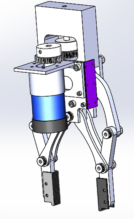
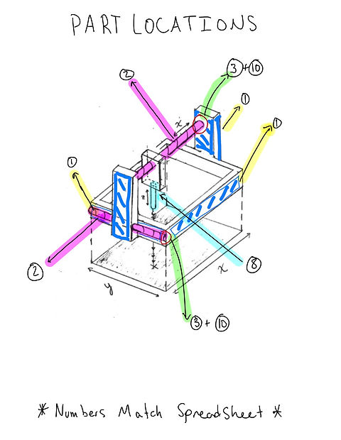
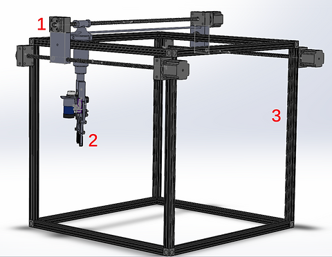
The design process for this crane began with creating a support system that could withstand a mount for the grabber of the crane. Two lead screws were attached to the servo motors to create the moving path for the crane's grabber. A linear actuator gave the grabber movement in the z-axis, an up and down motion. The crane is divided into three main assemblies, the carriage (1), grabber (2), and frame (3).
RESULTS
This project was divided between the four group members of the team. Each member contributed ideas, CAD parts, and assisted in the assembly of the 2.5-D mini crane. Our group was incredibly impressed at what we could achieve. Beginning this project, we were out of depth, especially with using mechanical stimulation tools. However, working together we were able figure out how to get out individual components to move together. The grabber portion of this project was especially difficult, as it is a complex mechanism that involves a linear actuator. This project was successful in giving students experience with advanced CAD tools and working with projects out of our league, but feasible with hard work. In the future, further improvements involve interchange end-effectors, a more compact carriage system, and an improved guide rail that would decrease sway.